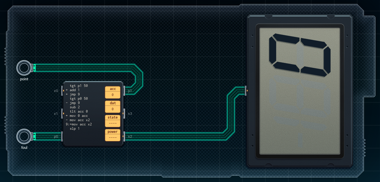
There's an early-game puzzle in SHENZHEN I/O called "BRING OUT THE BARON!!" that has you designing a simple personal scorekeeper for a drinking game. This assignment comes in through Joe, obviously.

The scorekeeper is a fairly simple device. It has two input buttons called "point" and "foul", and a multi-digit 7-segment LCD for displaying the score. Whenever the "point" button is pressed, the score should increase by one. The "foul" button decreases the score by two (but never below zero). Like I said: very simple. Here's one possible solution:
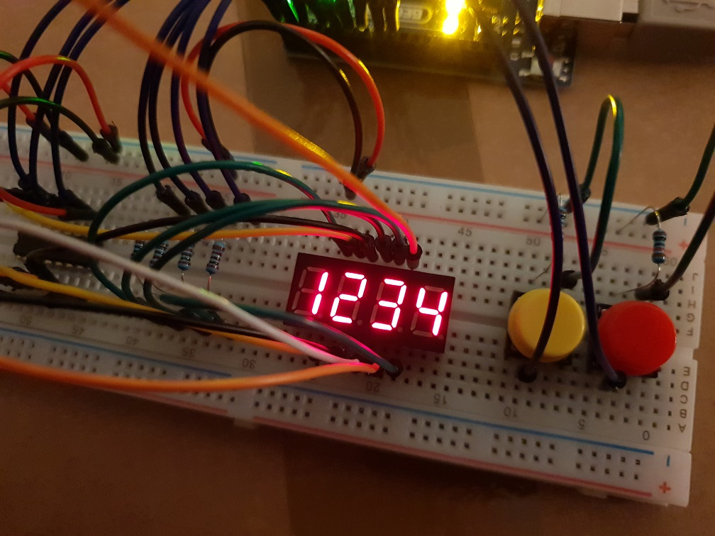
Rather than have this brilliant invention forever remain in the virtual world of SHENZHEN I/O, I thought it might be fun to bring it to life using real hardware components. So, in the remainder of this post, we'll build the "BRING OUT THE BARON!!" scorekeeper using an Arduino Uno.
Here's the list of the components needed:
- 1x Arduino Uno
- 1x large breadboard
- 28x breadboard line
- 2x pushbutton
- 2x 10k Ohm resistor
- 4x 1k Ohm resistor
- 1x 3461AS 4-digit 8-segment LED display
- 1x 74HC595 8-bit shift register
And here is the design we'll use:
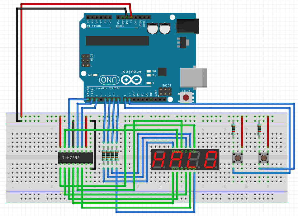
It's slightly more complicated than the one from SHENZHEN I/O, mainly because we have to actually build our own display driver instead of just sending the value we want to display to an XBus port.
The buttons are fairly simple, so let's start with those. They are connected to 5V and to GND through a pull-down resistor (10k) on one side, and to an input pin on the Arduino on the other. Pushing the button connects the Arduino pin to 5V, causing it to read a HIGH value. Conversely, the Arduino pin reads LOW when the button is not pressed.
On the coding side, the buttons are a little more interesting. Of course, any code we write will run in a real-time loop on the Arduino hardware and will directly deal with the digital or analog signals on its pins. There's no such thing as an event handler that nicely fires once and only once when a key has been pressed. If we want anything like that, we'll have to write it ourselves.
Here's the code I'm currently using for the buttons:
const int PIN_POINT = 8;
const int PIN_FOUL = 9;

bool button_pressed = false;

int score = 0;

void setup() {
  pinMode(PIN_POINT, INPUT);
  pinMode(PIN_FOUL, INPUT);
}

void loop() {
  if (digitalRead(PIN_POINT)) {
    delay(20);
    if (digitalRead(PIN_POINT) && !button_pressed) {
      button_pressed = true;
      point();
    }
  } else if (digitalRead(PIN_FOUL)) {
    delay(20);
    if (digitalRead(PIN_FOUL) && !button_pressed) {
      button_pressed = true;
      foul();
    }
  } else {
    button_pressed = false;
  }
}

void point() {
  score++;
  if (score > 9999) {
    score = 9999;
  }
}

void foul() {
  score -= 2;
  if (score < 0) {
    score = 0;
  }
}
Here's how it works: We constantly read the button input pins. As soon as we detect a signal from one of them, we wait a short while and then check again to see if the signal is still there. This latter part is called a software debounce. It's probably not needed, but it's more of a best practice that will filter out any noise from being falsely interpreted as a button press. Regardless, when we've detected a button press, we set the button_pressed flag and call the appropriate function to handle the press. The button_pressed flag only gets reset when no more signal is detected (and therefor the button has been released). This ensures we'll only call the handler function once for each press.
Now we can keep the score in memory, but we still need to display it. Here's where things get interesting on the hardware side. First, let's take a look at the display we're using. It's an 3461AS 4-digit LED display. Some googling and browsing through Chinese datasheets reveals the pin layout is as follows:
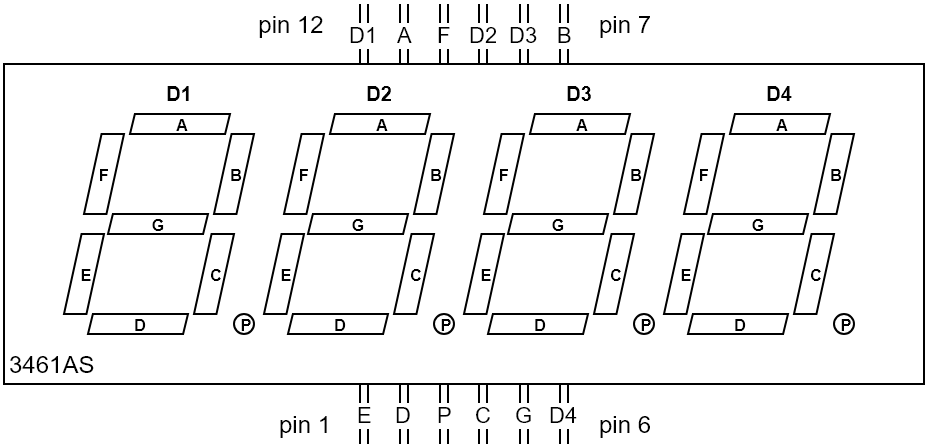
It's fairly straightforward. The A through P pins control the individual segments that make up the digits. The D1 through D4 pins control which digits are switched on. So in order to display a "4" on the first digit, we would need to power the respective pins for segments B, C, F, and G. We would then need to unpower the D1 pin, and power the D2, D3, and D4 pins.
Why?
Well, this is what's know as a common cathode display. This means the cathodes of all the individual LED segments are connected together. In order to use the display, we need to apply power to the segments we want to turn on, and then ground the common cathode connection. In this case, the common cathode connection for each digit is the corresponding Dx pin (D1 for the first digit, D2 for the second one, etc).
But wait, how do you display multiple digits?
Here's where things get fun. The display itself it stateless. It has no memory. You can't simply tell it: "hey, I want this on the first digit, and this on the second one." All it can do is show you the results of the signals that are being sent to its pins at that particular moment. If you enable D1 and D2 simultaneously, both the first and the second digit will look exactly the same. So the answer is that you can't display multiple digits. The best you can do is trick people into thinking that you can. If you show a "4" on the first digit for one millisecond, and then show a "2" on the second digit for another millisecond, and then show the "4" again, etc etc, it will appear to any human observer that the display is showing "42". The digits are simply being switched on and off faster than the human eye can tell, but are effectively still emitting light half of the time (in the case of two digits).
In our design, we connect the Dx pins to the Arduino directly (on digital pins 4 through 7), so it will control which digits are turned on at each moment. The display's segment pins are not controlled by the Arduino directly, but indirectly through the 74HC595. So how does that thing work? Well, the 74HC595 is an 8-bit shift register. The main advantage of using this component is that we only need to connect three of its pins to the Arduino, which in turn lets us control eight output pins. Here is its layout:
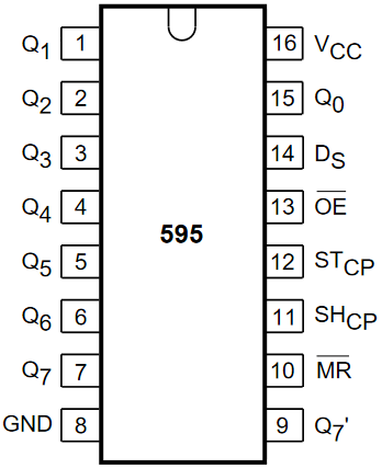
The Q0 through Q7 pins are the output pins. Yes, that means this thing has a whopping eight bits of memory. But in our case, that's enough to make up a digit for our display. We communicate with the 595 through its serial data pin (14), its shift register clock pin (11), and its storage register clock pin (12, also know at the latch pin). The power pin (16) and master reset pin (10, active low) are connected to 5V. The ground pin (8) and output enable pin (13, active low) are connected to GND.
Basic operation is as follows:
- Set the latch pin to LOW, so that new data can be received.
- Set the data pin to HIGH or LOW, depending on whether the bit you want to communicate is a one or a zero.
- Pulse the shift register clock pin.
- Repeat steps 2 and 3 until you have communicated all eight bits.
- Set the latch pin to HIGH.
When you're done, the eight output pins will light up (or not) according to the bit pattern you've just sent to the 595.
If you're at all confused, just follow this handy timing diagram:
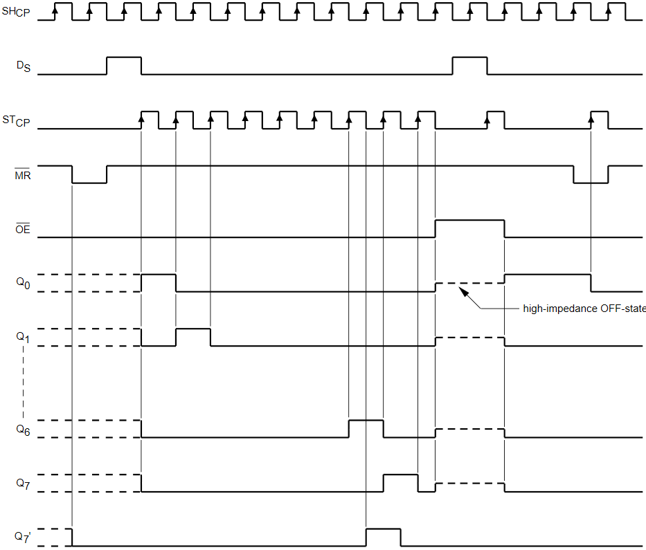
...or you can just use the shiftOut(...) function and not worry about all of these silly details. Yes, this is apparently such a common thing to do, there's a dedicated function for it right in the Arduino SDK. You feed this function a single byte, and it will handle communicating the individual bits to the 595.
Okay, so what data do we feed it?
In our design, the Q0 through Q6 pins (we don't use Q7) on the 595 are connected to the A through G pins on our display component. If we want to display a "3" we would need to power the respective pins for segments A, B, C, D, and G. These correspond to pins Q0, Q1, Q2, Q3, and Q6 on the 595. In binary, this makes 0100 1111 (Q7 is the leftmost bit, or the most-significant bit) that we would need to store in the 595. In decimal, this could be 79 (0100 1111) if we send the most-significant bit first to the 595, or 242 (1111 0010) if we send the least-significant bit first. Regardless of how we send it, once we've done so we can then use the Dx pins on the display to show our number in any of the four digits.
Here's the code I'm using to display the current score:
const int PIN_CLOCK = 2;
const int PIN_DATA = 0;
const int PIN_LATCH = 1;
const int PIN_D1 = 4;
const int PIN_D2 = 5;
const int PIN_D3 = 6;
const int PIN_D4 = 7;

// [...]

const int WRITE_DELAY = 2;

// [...]

int numbers[10] = {
  63,  // 0
  6,   // 1
  91,  // 2
  79,  // 3
  102, // 4
  109, // 5
  125, // 6
  7,   // 7
  127, // 8
  111  // 9
};

void setup() {
  pinMode(PIN_CLOCK, OUTPUT);
  pinMode(PIN_DATA, OUTPUT);
  pinMode(PIN_LATCH, OUTPUT);
  pinMode(PIN_D1, OUTPUT);
  pinMode(PIN_D2, OUTPUT);
  pinMode(PIN_D3, OUTPUT);
  pinMode(PIN_D4, OUTPUT);

  // [...]

  digitalWrite(PIN_D1, HIGH);
  digitalWrite(PIN_D2, HIGH);
  digitalWrite(PIN_D3, HIGH);
  digitalWrite(PIN_D4, HIGH);
}

void loop() {
  // [...]

  draw_score();
}

// [...]

void draw_score() {
  if (score < 0 || score > 9999) return;

  draw_digit(score % 10, PIN_D4);

  if (score > 9) {
    draw_digit((score / 10) % 10, PIN_D3);
  }

  if (score > 99) {
    draw_digit((score / 100) % 10, PIN_D2);;
  }

  if (score > 999) {
    draw_digit((score / 1000) % 10, PIN_D1);
  }
}

void draw_digit(int value, int digit_pin) {
  digitalWrite(PIN_LATCH, LOW);
  shiftOut(PIN_DATA, PIN_CLOCK, MSBFIRST, numbers[value]);
  digitalWrite(PIN_LATCH, HIGH);
  digitalWrite(digit_pin, LOW);
  delay(WRITE_DELAY);
  digitalWrite(digit_pin, HIGH);
}
I've omitted any code I've already shown in the previous snippet. That code deals with the buttons and scorekeeping, while this code deals with displaying the score.
Operation is fairly straightforward. Initially, all Dx pins are set to HIGH so that the display is effectively turned off. The draw_score function is responsible for showing the score on the display, and gets called at each program loop. It breaks down the score into its individual digits, then passes those to the draw_digit function. This function performs the actual drawing. First, the latch pin of the 595 is set to LOW. Next, the bits that correspond to the requested digit are sent to the 595 using the shiftOut function. The bits for each number are stored in a lookup array. Once they've been sent to the 595, the latch pin is set to HIGH. This stores the bits in the storage register and outputs their values on the Q0 through Q7 pins. Finally, we pulse the Dx pin that was requested. We first set it to LOW, wait a short amount of time, and then set it to HIGH again. This effectively displays the requested number on the requested digit for a very short amount of time (2 milliseconds, in this case). Doing this constantly, hundreds of times per second, results in a nice, clean displaying of the score.
Of course, phones that happen to have super-slomo cameras on them aren't fooled quite so easily...
According to Samsung, the super-slowmo part of this video (which starts at about 2 seconds in) should be running at 960 frames per second, which would mean one second of that 30 fps video is around 32 milliseconds real-time. Manual counting shows each number pulsing four times in one second of video, which comes down to one pulse every eight milliseconds. Looking back at our display code, we've programmed in a two millisecond pulse for each number, meaning it takes eight milliseconds to display all four numbers once. Math: checks out.
Anyway, this just about wraps things up as far as our scorekeeper is concerned. I hope Joe's happy with the design, although last I heard he was busy "sampling" some of the Baron von Schnapps that was sent to the Longteng Electronics Co. offices, so I think he'll be happy regardless. As for me, I'm off to the next project. I heard Carl talking about some "rubbish audio thing" that needs building...