We're continuing our dream of becoming a world-class embedded systems engineer. Well, a virtual one, at least. This is more programming puzzling with SHENZHEN I/O.
Assignment #4: eSports sign
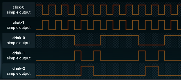
For this assignment we need to create an animated eSports sign. It just consists of a series of lights that need to flash in a certain pattern.
So, let's see what we can do here.
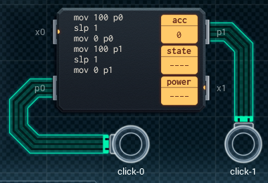
We'll first tackle the two "click" outputs. We'll just need to invert them every time unit, which is pretty straightforward. We'll use a single MC4000 for this. Here's the design:
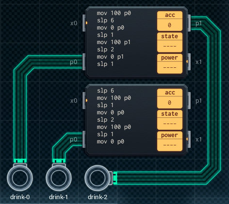
The three "drink" outputs are next. Since we don't have any components (yet?) with three or more I/O pins, we're forced to use two of our familiar MC4000s. Now it's just a matter of deciding which MC4000 handles which two outputs, and which handles the remaining one. Looking at the patterns, I first figured I might be able combine "drink-1" and "drink-2" using some clever code. Unfortunately, I quickly ran into a limitation: you can only write 9 instructions into the MC4000. Combining "drink-1" and "drink-2" requires 10 instructions. So that won't fly.
Instead, I'll have to put "drink-1" on its own MC4000, and let the other MC4000 handle "drink-0" and "drink-2". Here's how that looks:
And that's another assignment completed!
Assignment #5: harmonic maximization engine
My coworker Carl calls this a "rubbish audio thing". Little does he know I am a rubbish electronics engineer, so this is right up my alley. Our input consists of an audio stream (just a regular I/O signal) and a button. We need to do some transformation on the audio signal if the button is pressed. Otherwise, we just pass the signal through as-is.
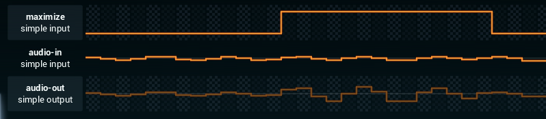
The transformation itself is contained in the following formula:
AUDIO_OUT = (AUDIO_IN - 50) x 4 + 50
So, it looks like we'll be doing some basic math this time. Before we start designing our components, it's interesting to note that we can simplify the formula as follows:
AUDIO_OUT = 4 x AUDIO_IN - 150
The second thing to note it that we're dealing with three I/O ports, while all of the components we can work with so far (the MC4000 and MC6000) only have two I/O ports each. It looks like we'll need to combine at least two of them together, and have them communicate internally through the XBus ports.
Time to RTFM again and figure out how the XBus protocol works.
XBus ports seem to be intended for inter-component communication. They're just registers, like the I/O ports, but unlike I/O it looks like XBus is a synchronized protocol. You can only transfer data if writing and reading occurs simultaniously. What's more, any read or write on an XBus pin will block until a write or read is performed on the other side, respectively. Fortunately, there's a useful helper instruction to deal with this:
slx x pauses program execution until there is data available for reading on the XBus pin x.
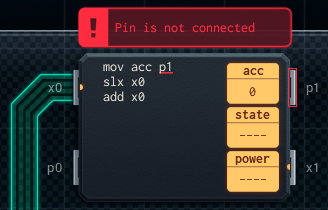
Alright, time to build the first component. This will be an MC4000 responsible for reading the audio signal, and applying the transformation if the button is pressed. I've come up with the following design:
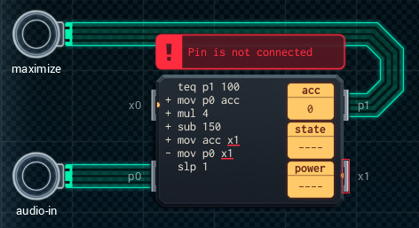
The math takes place entirely in the accumulator. There's also a new instruction here:
sub x subtracts x from the value in acc, and stores the result back into acc.
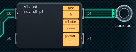
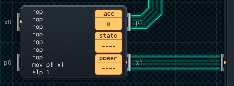
After the transformation, we pass the resulting value to the x1 pin. If the button isn't pressed, the audio signal is simply passed to the x1 pin directly. This just leaves us with connecting the x1 pin to something. We'll use another MC4000, which simply reads the value from its corresponding XBus and passes it on the the I/O pin connected to the audio output. Something like this:
...aaand we're done!
Assignment #6: drinking game scorekeeper
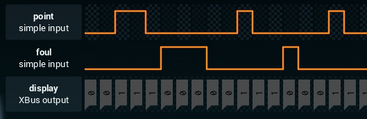
This assignment requires us to create a simple scorekeeper. Basically just a counter. There are two buttons, one for increasing and one for decreasing the score. The score itself must be communicated to an LCD display over XBus.
Design #1: just getting it to work
I figure the main difficulty here is dealing with the fact that button presses can take up multiple time units, yet the score must only change once when the value of the button input turns from low to high. Therefor, the first thing I'll need to build is some kind of pulse shortener. To build it, we'll need to introduce another new instruction:
jmp x moves program execution to label x. I'm sure Dijkstra is already rolling in his grave.
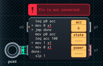
As for the pulse shortener, I came up with this:
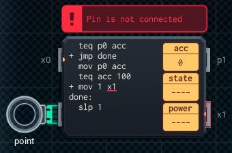
This sends a value (in this case 1) to x1 when p0 moves from 0 to 100. I add two pulse shorteners (one for each button), and connect both their x1 outputs to the same x0 pin for my counting module.
This waits for any XBus communication, and then just adds the value sent (-1 or 1) to the accumulator, which contains the score. However, there are some problems. XBus is a synchronized protocol, and blocks whenever no values are sent. But we need to send the score to the display each time unit. So we can't do that from the counter like this, not while using slx. My first solution to this was to send the score over the p1 pin to yet another MC4000:
However, as you can see, I was in trouble again due to the fact that the I/O protocol is non-blocking. As a result, the final component would often read the p1 pin before its new value had been set. The solution: a whole bunch of nop operations (which do nothing), to ensure reading of p1 occurs after the rest of the components have finished doing their thing. Not exactly the prettiest of solutions, but funny enough it did work. Oh how this game is already so lifelike.
I'm not satisfied to leave it like this though, so I'm making a new design to see if I can come up with something better.
Design #2: refinement
I'll modify my pulse shorteners to always send a value over the XBus pin, instead of only when the button is first pressed. It'll be 1 on the first press, and then 0 at all other times. Like so:
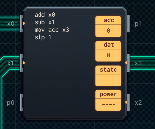
Next, we'll shell out the extra 2 yuan for an MC6000, because we need three XBus pins. Instead of combining the XBus wires like we did on the first design, we'll send each button's wire to a separate XBus pin. We can do this because there'll always be a value sent (0 or 1), so it won't block when a button isn't pressed. We can then simply read the values from the two XBus pins and add/subtract them to/from the accumulator. Finally, the score is sent over the third XBus pin to the display.
It's easy to see that this is a much better design. Not only does it pass the test (that's fairly important), but it's cheaper and uses less power than design #1. But most importantly, it doesn't depend on weird program timing.
I'm happy with this, so we'll let it be and move on to the next one. That's for another day, though...