After a 40 hour work week of computer programming, what better way to spend a saturday than more programming? For no pay? For a non-existent company? This is what it's all about with SHENZHEN I/O. On to our next assignment!
Assignment #7: infrared sensor
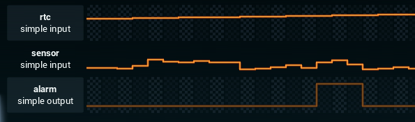
We've received an email from Lily Wu, Vice President of Product, tasking us with the design of a passive infrared sensor. This must be important. We are supposed to read out sensor values, and, if they exceed a certain threshold within a specified time of day, send out an alarm.
There's a couple of special components already on our design surface:
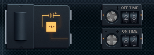
The left one is a clock, which produces a signal indicating the time of day. The right ones are on/off switches, which produce a comparable signal also indicating some time of day. The clock uses an I/O pin, while the switches use XBus. We start off by building a component which compares the values of the on/off switches to the current time, and sends out a simple signal indicating indicating if the alarm should be "armed". We'll be needing some more conditional instructions today:
tlt x y determines if x is less than y.
tgt x y determines if x is greater than y.
Our time checking component looks like this:
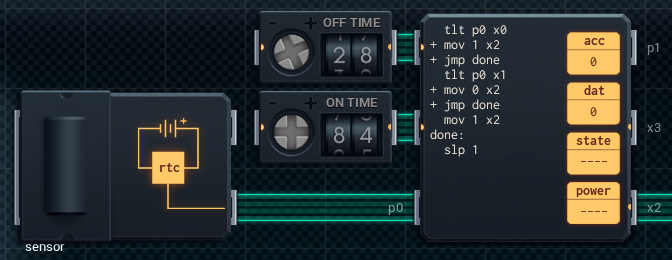
There was a bit of fiddling when figuring out whether the on/off values should be inclusive or not. Turns out they're both inclusive, in the way that the value of the "on" switch counts as the alarm being armed, and the value of the "off" switch counts as the alarm being disabled. So, simply put:
ALARM_ON := TIME_ON <= CURRENT_TIME < TIME_OFF
This component communicates a 1 over its x2 pin if the alarm is armed, and a 0 otherwise. This value is then read by the sensor-checking component.
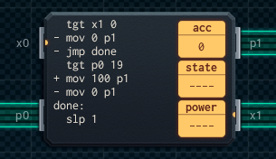
Again, trial and error was needed to figure out that the alarm-triggering sensor value of 20 was inclusive. It's a shame the language doesn't contain greater-or-equals and less-or-equal instructions.
Anyway, that's all for this assignment. Another job well done.
Assignment #8: buzzer
For our next design we'll need to create a radio-controlled buzzer. We'll receive either 0, 1, or -999 from a radio receiver over an XBus pin. The special case with this radio component is that its XBus pins don't block. You'll always receive something, with -999 being used as a null value. For this reason it makes no sense to use slx, because there'll always be a value to read. Additionally, we can only read the value from the pin once. After that, it's back to -999. So the first operation must be a move to a register. We can then process it further from there. Once we've received a 1, we'll need to start sending 1t pulses to an I/O pin connected to a buzzer. We'll need to keep doing this until a 0 is received.
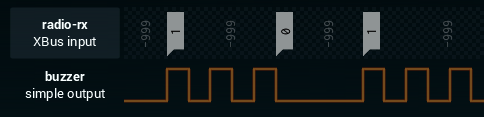
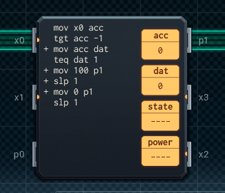
This one is pretty easy. We'll just need to store the last proper value we've received (0 or 1), ignoring the -999 garbage. Then as long as the value is a 1, we send out a 1t pulse. We'll need two registers, so an MC6000 it is. Here's my design:
Done and done! Next!
Assignment #9: device 2A27
This time we have been approached by a company that's fully run by AIs. I guess we're taking orders from computers now, too. No worries, let's just see what the spec is about. It seems we have two inputs (x and y), and we need to map them to a single output value, according to the map below:
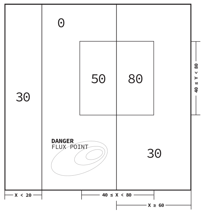
This won't really be too difficult; the challenge will be building something efficient and compact. The key is realizing that we can use addition. The two outer-most columns (x < 20 and x >= 60) add 30 to the final output value, and the square in the middle adds another 50. If something is in both the right-most column as well as the center square, 30 + 50 makes 80, as required.
We'll first build the component that handles the center square:
This is the only component that needs to acces both I/O input ports, so we'll put this first in the chain. That way, the second component can use its free I/O port for the output value. Anyway, the first component checks if the (x, y) position is inside the center square, and if it is, it sends a value of 50 on its x0 pin. Otherwise, a value of 0 is sent.
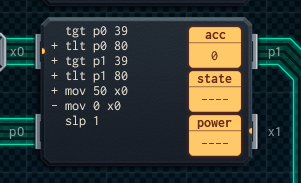
The second component deals with the outer-most columns:
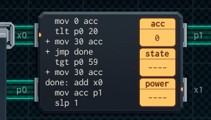
It only has to check if the x value is within certain constraints. If it is, a value of 30 is added to the accumulator. Next, the value from x0 is read and added to the accumulator. The result is then sent to the output on p1.
And that's another job well done!