Have you ever dreamt of moving to China to work as an embedded systems engineer? Me neither. Fortunately, a recently released video game will now let you live out the fantasy you never knew you had.
SHENZHEN I/O is a programming puzzle game, where you design and program circuits. Everything I saw about it looked great, so I bought it. And I figured it’ll be fun to document my journey for my blog. The journey of a thousand miles begins with a single step, and our first step is flying to Shenzhen, China.
But first, RTFM
This game is… special. To say it comes with a manual would be an understatement. Rather, it comes with about 30 pages worth of technical documentation for all sorts of (fictional) hardware components, as well as a toy assembly language used for programming them.
I’m guessing if we want to have any hope of succeeding, we’ll need to become intimately familiar with all of it, but for now we’ll just read stuff as-needed.
Assignment #1: fake security camera
At the start of the game, we are freshly employed by the Shenzhen Longteng Electronics Co. Ltd. Our first assignment is creating a fake security camera. It has two lights (“active” and “network”), and we need to design a circuit that makes the lights blink in a certain pattern.

The “active” light needs to be off (signal of value 0) for 6 “time units”, then on (signal value 100) for 6t, off for 6t, etc. The “network” light has a slightly more complicated pattern. The circuit for the “active” light has already been completed by our predecessor (who quit for mysterious reasons).
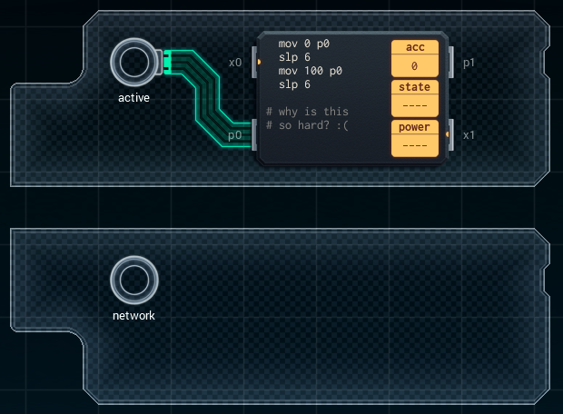
It consists of an MC4000 microcontroller, with its p0 pin connected to the light. The programming is very simple, and makes use of two different instructions.
mov x y moves value x to register y, where x can be either an integer, or another register.
slp x pauses program execution for x time units.
Building the circuit for the “network” light is left up to us, but we already have all the information we need to complete this assignment. We’ll add a second MC4000 and connect its p0 pin to the “network” light. The programming is as follows:
  mov 0 p0
  slp 4
  mov 100 p0
  slp 2
  mov 0 p0
  slp 1
  mov 100 p0
  slp 1
We simply move either 0 (off) or 100 (on) the the p0 pin to control the light, and then sleep for whatever duration the light needs to be in that state. When we run a simulation of the system, it unsurprisingly works as expected. First assignment complete!
Assignment #2: signal amplifier
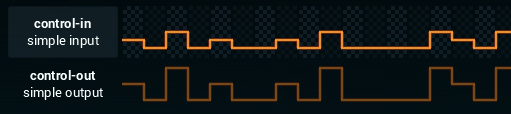
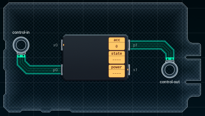
Our second assignment is to build a signal amplifier. It’s a very simple one: we just have to read a signal from an input port, multiply it by 2, and send that to the output port.
We’ll hook up our trusted MC4000 like so:
As for programming, we’ll need to learn a new instruction:
mul x multiplies the value in the acc register by x, and stores the result in the acc register.
Coding this will be easy!
  mov p0 acc
  mul 2
  mov acc p1
  slp 1
Our program moves the input value from the p0 pin into the acc register, multiplies it by 2, and then moves the result (which will also be in the acc register) to the p1 pin. Finally, we sleep for the remainder of the time unit. And that’s it for that one!
Assignment #3: pulse generator
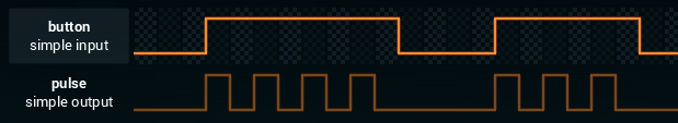
For our next assignment, we’re tasked with designing a pulse generator. We’ll need to generate pulses according to a certain pattern, while a button is pressed.
For this, we’ll need to RTFM on conditional execution. Turns out this doesn’t work entirely as expected. Instead of doing conditional jumps or something like that (as you might expect from assembly), your conditional tests can simply enable or disable individual lines of code. Prefix a line with a “+” sign, and it becomes enabled whenever a conditional (e.g. an equality check) is true, and disabled if the check returns false. Lines prefixed with a “-“ sign work in reverse. Lines without any prefixes are always executed.
We’ll use the following instruction for our conditional execution:
teq x y tests whether the value of x equals that of y.
After some fiddling, I came up with the following solution:
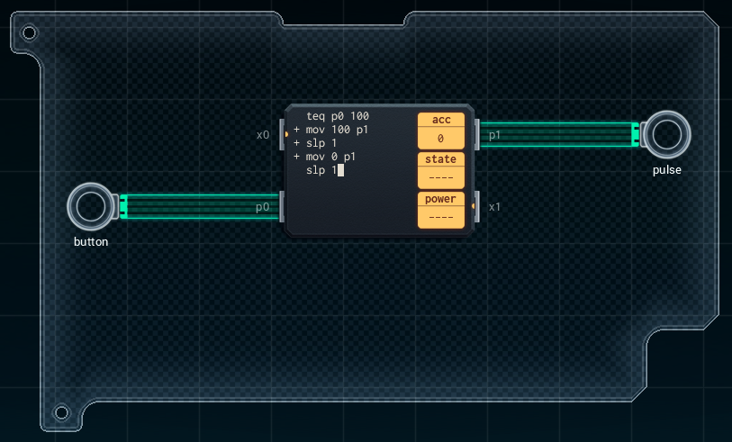
This check whether the button is pressed, and if it is, generates a single pulse that’s on (100) for 1t and off (0) for 1t. The code is kept simple by taking advantage of the fact that a pulse can never be interrupted, and a pulse of 100 must always be followed by at least 1t of 0.
In case you want to copy/paste, the code is:
  teq p0 100
+ mov 100 p1
+ slp 1
+ mov 0 p1
  slp 1
And that’s the third assignment done.
Wrapping up
I’ll end this post here for now. We’re still very much in the tutorial part of this game. Later puzzles will undoubtedly be much, much harder. I’m already looking forward to getting hopelessly stuck!