Time for some more electronics engineering with SHENZHEN I/O.
Assignment #10: color-changing LED
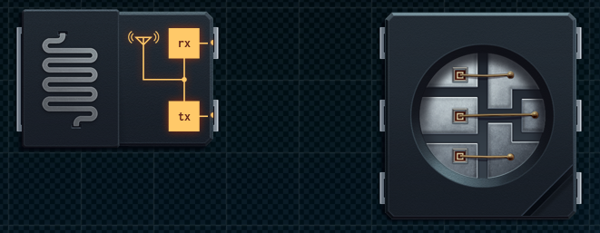
In this design we’re supposed to change the color of an RGB LED light, based on signals we’re receiving over a radio. The radio and the LED are already on the design surface:
The radio signal is received through a non-blocking XBus pin, while the LED has three I/O pins that control the intensity of the individual red, green, and blue LEDs. The information we receive from the radio contains four values of data per time unit, or the usual -999 for null.
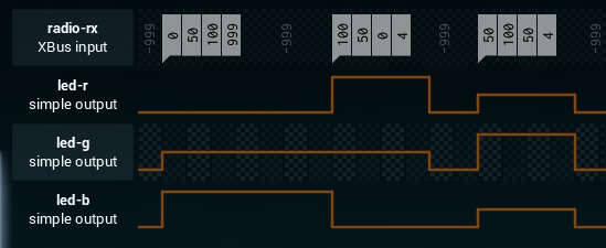
The four values contain the information for controlling the LED, like so:
| red_intensity | green_intensity | blue_intensity | duration |
Hence, when we receive a packet, we need to set the colors of the LED for as many time units as specified, and then turn it off afterwards. If we receive a new packet, we can update the LED regardless of its current state.
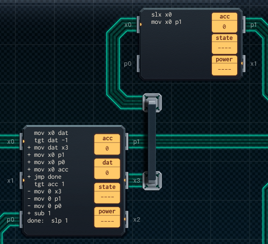
So, let’s build it. I started out with an MC4000, but quickly realized that the extra register and larger instruction memory of an MC6000 are needed. I hook the MC6000 up to the radio, and connect its two I/O ports to the green and blue ports of the LED. The signal for red is sent over XBus to an MC4000, which then simply passes it along to the LED on its I/O port. Here’s what my setup looks like:
On the MC6000, the acc register is used to count how long the LED should remain on. The dat register is used as temp storage for data that’s received from the radio. The code in the MC6000 does two things:
- It checks if new data is received (which would be non-negative values), and if it is, it reads it, sends the color values along on their respective ports, and stores the duration value in the accumulator.
- If no new data is received, it checks there’s still “time” left on the accumulator. If there is, it subtracts 1 from acc. If not, it moves all 0 values to the three color ports.
Phew. Only just managed to fit that one in a single controller. All tests are green, so job well done!
Assignment #11: wireless game controller
This one sounds fun. We’ve been asked for assistance by my coworker Carl. He needs some help on a game console he’s working on, specifically on the controller part. In his design, the console pings the controller over a radio, and when it does we’re supposed to return information about the state of the controller (joystick position and which buttons are pressed) back over the radio.
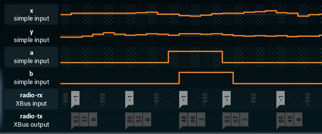
The game controller has two joysticks (“x” and “y”), and two buttons (“a” and “b”). They’re all simple I/O ports to us. The packet we’re supposed to send back should look as follows:
| x | y | button_encoding |
The values for “x” and “y” are just the last reading from the joystick I/O ports. The button_encoding field should be 0 if no buttons are pressed, 1 if only “a” is pressed, 2 if only “b” is pressed, and 3 if both are pressed. So, roughly like this:
Alright, let’s get to it.
Design #1
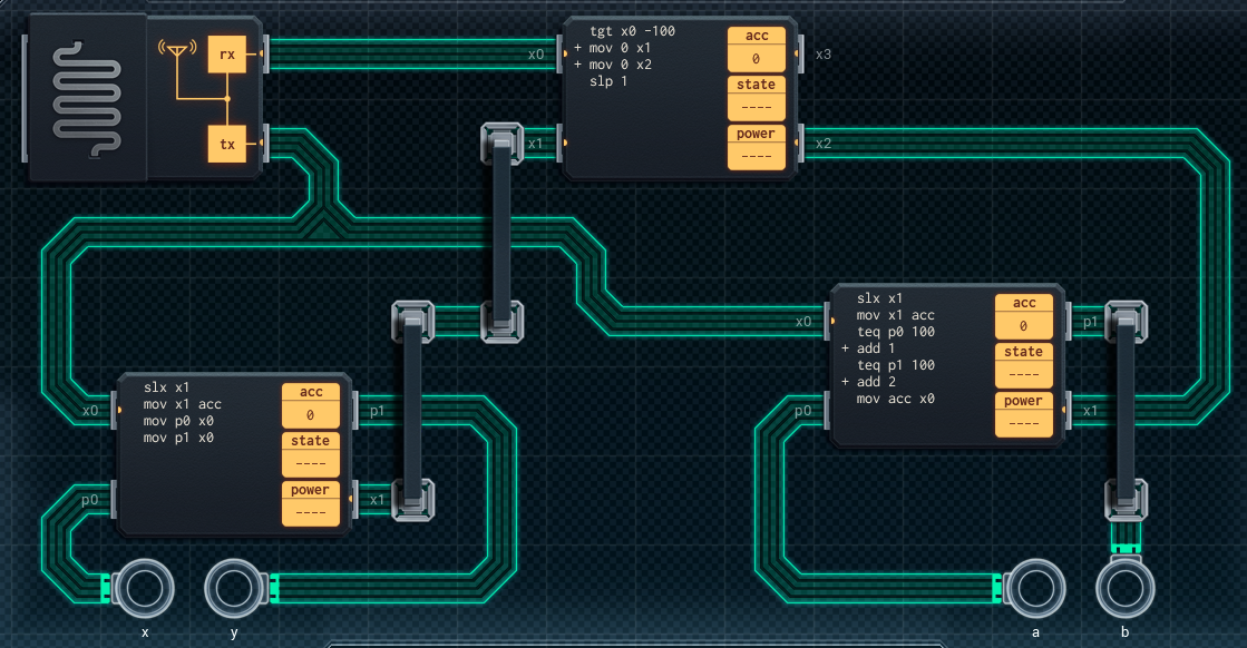
Since there’s too many I/O ports to be read by a single controller, we’ll obviously need at least two. So that means coordinating between the two “readers” to make sure the values are transmitted in the correct order. My first instinct was to have a dedicated “coordinator” to arrange this. This lead me to the following design:
The middle MC4000 is the coordinator, while the left and right MC4000s are the readers. The coordinator listens on the radio, and directs the readers to read as soon as a ping has been received. Both readers are hooked up to the transmitting port of the radio. They wait for a signal from the coordinator, and when they receive it they send the current I/O port values to the transmitter.
What’s interesting (or annoying) here is that I found out that after an slx, you also need to perform some action that actually reads from the corresponding XBus pin. If you don’t, the write blocks. So you can’t really use XBus and slx as a signalling mechanism, at least not in the way I intended. If you’ll note, the left MC4000 has a wasted mov instruction that simply completes the XBus handshake by reading from the x1 port without actually using the value for anything. However, over on the right MC4000, I use this “feature” for resetting the acc register, which needs to happen anyway.
This design works and is quite reasonable, but I can do better…
Design #2
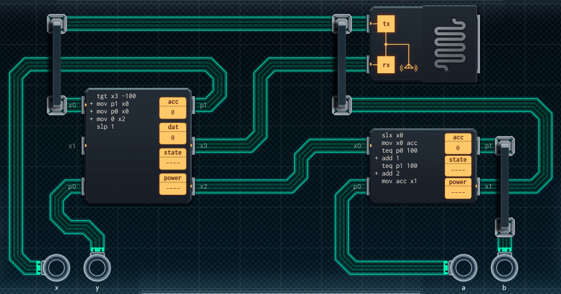
After completing design #1, I quickly realized I’d be able to combine the coordinating and the reading of the joystick values into a single MC6000. The most difficult part was actually getting the wiring done right. I ended up with this:
As I’ve said, this simply combines the coordinator and left reader from the previous design into a single MC6000. This makes the design a single yuan cheaper, and also more power efficient. Not bad…
Assignment #12: payment kiosk
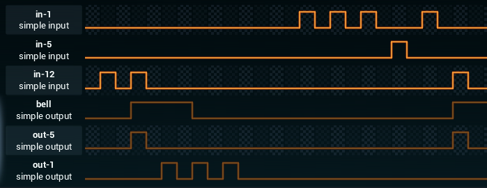
Our next assignment comes from our weeaboo coworker David, who has negotiated a deal to provide payment kiosks to some kind of theme park. Our kiosk can receive coins worth 1, 5, or 12 yuan. When the money received exceeds a certain treshold, we’re supposed to ring a bell (I/O port) and dispense any change using 1 or 5 yuan coins (I/O ports).
The price is specified using what looks like a D80C010-F, already on the board. This looks like it might get interesting, so let’s get started…
Design #1
As expected, the main difficulty here is the change dispensing. Here’s my first design:
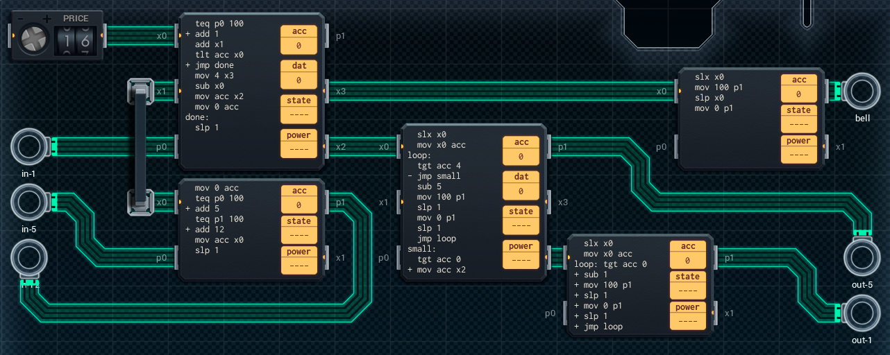
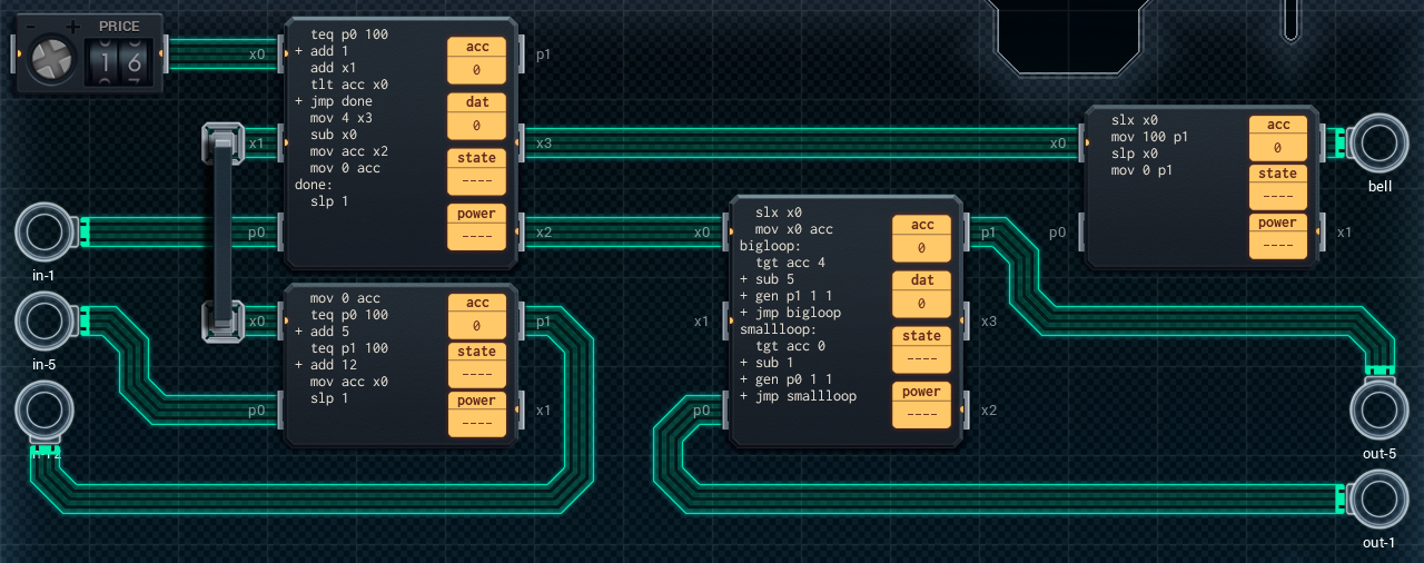
It’s… quite something. On the left, an MC4000 and MC6000 read the coin inputs and keep track of how much money is currently in the system. The MC4000 on the bottom reads both the 5 and 12 yuan coin slots, and passes the current value (0, 5, or 12) on to the MC6000 over XBus. The MC6000 reads the 1 yuan coins, and is also responsible for keeping track of the total amount of money received. When this amount passes the amount set by the price control, two signals are sent out: one to an MC4000 responsible for sounding the bell, and one to the change dispensing mechanism.
I could only barely fit the change dispensing logic into a combined MC6000 and MC4000. They work in tandem: the MC6000 receives the amount of change that needs to be dispensed and dispenses 5 yuan coins while this is possible. Then, it sends any remaining change to the MC4000, which dispenses the 1 yuan coins. The problem with keeping this stuff compact is the fact that these damn mov, slp, mov, slp instructions take up so much space. If only there was a way of compacting this…
Design #2
I remeber an email my coworker Carl had sent me a few days earlier. In it, he mentions an undocumented instruction for the Chengshang Micro microcontroller we use everywhere. The instruction is called gen and it’s basically syntactic sugar for a pulse generator. This:
gen P X Y
…is equivalent to this:
mov 100 P
slp x
mov 0 P
slp y
Well then. I have a feeling this will come in very handy. Time to revise our payment kiosk design! I’m only changing the change dispensing logic, to take advantage of the gen instruction. Here’s the new and improved design:
This saves us 3 yuan on the MC4000 we no longer need, as well as being slightly more power efficient. We’ll leave it at this for now.
